History of the C-52 and CX-52
The Cipher or Decipher mode is selected with a knob on the left side. To encipher the operator turns the large letter knob on the left side until the desired letter appears on the letter dial and pushes the lever on the right side of the machine downwards. In Cipher mode the letters are printed in groups of five letters and the letter X is used to replace a space. In Decipher mode there are no groups and a deciphered letter X is replaced by a space. When the counter is reset, this also will reset the group counting of the printing mechanism. The unit can be attached to a separate electrical motorized keyboard. The combination of C-52 or CX-52 and B-52 electrical keyboard is called BC-52.
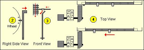
If a guide arm is in the active position (when the pin on the current wheel is set) [2] during the revolution of the drum all lugs on bars in that position will contact the active guide arm. Those bars are forced to slide to the left [3]. The left side of the drum works as a variable-toothed gear [4]. Each bar that is slid to the left is one more tooth on the drum. The drum will turn the gear from the printing wheel. Therefore, the number of steps that are added to the plain letter is the number of teeth on the drum.
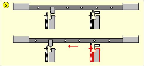
Wheel Movement The C-52 produces a constant stepping of the wheels, each with its own prime number of pins, resulting in a very long period of different wheel position combinations. On the CX model the movement of the 6 wheels depends on the settings of the lugs on the drum and the pins on the wheels, which results in a complex stepping. If we number the wheels from left to right the first wheel steps on each cycle of the drum. The other 5 wheels are moved by 5 special advance bars. Each of these bars is identical to the encryption bars but it also has small fixed pins. If a lug on such a bar contacts an active guide arm it will be forced to slide to the left, just as a normal bar. However, in the case of advance bars a little fixed pin at that bar will now be positioned right in front of a small gear wheel, which steps the pinwheel one step further. On the photo from the drum (above) we can see two small movement pins on the left side of bar number 5. In the example below [5] we can see that the current pin on wheel 2 is in the active position, and on the drum the advance bar for wheel 5 has a lug in position 2. The moment the drum revolves, that lug will contact the guide arm from wheel 2, push the bar to the left and let the small fixed pin advance wheel 5.
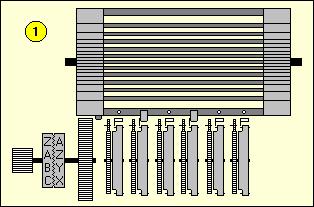
Setting the Machine Both sender and receiver must set their machine in exactly the same way. The key setting consists of six parts. The selection and order of the pinwheels, adjusting the pins on the wheels, the lugs, the advance bar lugs, the print wheel offset and the message key or initial start position of the pinwheels before enciphering a message. Pin Settings on the Wheels On the C-52 model the operator first selects 6 wheels from a set of 12 different wheels. These can be placed in any desired order in the machine. On the CX-52 model all wheels have 47 pins. Extracting the wheels is done by opening the cover and pull out the main wheel axle to the right. The experts recommend that a statistically random method be used in choosing a pattern for setting the pins. A simple way is flipping a coin and writing down the result (obverse = active pin, reverse = inactive pin). For an even distribution you should never allow more than 3 successive pins on any wheel to have the same state and try to have close to 50 percent of the pins on a wheel in the active position.
The Lugs on the Drum The lugs on the drum determine which bars will contact the guide arms of the wheels and force that bar to the left to act as tooth for the print wheel gear. The lugs are a vital part of the key setting and should be selected carefully. To create a good lug setting we select 6 numbers between 1 and 14 whose sum is 27. Assign each of these numbers to one of the 6 positions. Write down all 64 possible combinations of 6 pins for a given state of the drum. The easiest way to do so is to write them down in binary order (1 = 000001, 2 = 000010, 3 = 000011 and so on). For each possible combination of pins, find the sum of numbers which have an active pin. Write this sum to the right of that combination. If a sum is greater than 25, subtract 26 from it. Continue until you have all sums for all possible pin combinations. Finally, check whether the 64 sums include all possible numbers from 0 to 25. If this is not the case, discard the lugging set and make a new one. With a little experience you will be able to correct a bad lugging by changing only a few lugs. If we follow all these rules there are 35,100 different valid lug settings available. Example of a Lugging check table:
Once a good lugging is found, we can start placing the lugs on the slide-bars. Start with the first of the 6 selected numbers. In our example from above this is 13. Place a lug on the first position of the first bar (disregard the movement bars!) and continue until you have placed 13 lugs in the first position of the first 13 slide-bars. Proceed with placing 7 lugs in the second position of the next 7 slide-bars and so on. The Advance Bar Lugs on the
Drum The advance bars are responsible for the irregular movement of the wheels and are critical for the cryptographic security of the machine. If a bar is forced to the left by an active guide arm that contacts a lug, the wheel that is commanded by that bar will move. Bar 1 commands wheel 2, bar 2 commands wheel 3 and so on. Let us see what happens when the drum turns one complete cycle. We will use the example below to explain one good and one bad lug setting for the wheel movement. The bars move one by one by one past the guide arms and bar 1 is the first bar to pass the guide arms. A lug is represented by the letter X. Notice that more than one lug can be placed on a single bar. Wheel 1 always moves, no matter what state the lugs or pins have. If there's an active pin on wheel 1 then all 5 bars will be forced to the left since there is a lug in position 1 on each of the 5 bars. Therefore wheels 2, 3, 4, 5 and 6 will advance one step. An active pin on wheel 2 will move wheels 3, 4, 5 and 6. An active pin on wheel 3 will move wheels 4, 5 and 6, and so on. This creates a highly irregular wheel movement sequence, depending on the state of the pins on the wheels.
To show the importance of the selection of lugs on the advance bars we will examine an example of a bad lug setting. The problems are obvious. Wheel 2 will only move if there is an active pin on wheel 1. Wheel 3 only moves if there is an active pin on wheel 2 and so on. This results in a very slow rotation of the last wheels, limiting the pin variation and therefore weakening the security.
The special wheel movement bars in the early CX-52 setup are also used for enciphering. When using the movement bars also for enciphering the lugs, one must follow the rules as explained above, but also be sure to create a good stepping cycle for the wheels. Therefore, due to complications in preparation of acceptable lug patterns, later CX-52 models use the special movement bars exclusively for the stepping of the pin wheels and no longer had a tooth at their left side to advance the print wheel. There are different versions of the C-52 and CX-52. Some have fixed advance bars spread all over the drum instead of the normal first 5 bars. On some machine versions the advance bars are detachable and their order can be changed. Print Wheel Offset To add a complication to the encryption it is possible to use an offset on the print wheel. This is done by pulling the dial knob on the left away from the machine, thus disconnecting plain and cipher print wheels from each other, and then turning the dial a given number of steps. For example, when enciphering the letter H with an offset of 2 letters the machine will actually encipher the letter F.
Some machines are equipped with a Variable mode F-V switch, locate at the left side of the machine. In the Fixed mode, the two print wheels remain connected with each-other during the ciphering process. In the Variable mode, the position between left and right print wheel changes constantly. During a Variable mode enciphering cycle, the letter of the left wheel is printed first. Next, the two print wheels are disconnected and only the right wheel turns to its new position and prints. Finally, the two print wheels are reconnected again in the new position. In Cipher mode, the left print wheel prints the selected plain letters, and the right print wheel prints the encrypted ciphertext letters. In Decipher mode, the left wheel prints the entered ciphertext letter and the right wheel prints the decrypted plaintext letter. The Message Key The start position of the six wheels at the beginning of the message is called the message key. This message key is a crucial part of the cryptographic settings of the machine and must be unique for each encrypted message, in order to make optimal use of the key variations. If the same message key is used for many different messages this increases the amount of statistical information for a cryptanalytic attack on the message. There was no standard procedure to encipher messages. Each customer could create his own message procedure, of course assisted by the advice of the manufacturer. One part of the procedure is telling the receiver which message key was used for the transmitted message. One way to relay the message key is to include it into the message. However, the operator must encipher the message key before transmission in order to relay it in a secure way. This can be done by selecting a random message key (which is used to encipher the message), set a random start position for the six wheels and then encipher the selected random message key. Next, the random start positions and the enciphered version of the message key are sent together with the message. The receiver sets his wheels in the received random start positions, deciphers the encrypted message key, sets the retrieved message key as start position and deciphers the rest of the message. The procedure with the enciphered message key, as described above depends entirely on the secrecy of the machine settings. If these settings are compromised, then unauthorized persons can decipher the message. Some procedures use a second secret table with message keys in addition to the key settings sheet. Both sender and receiver use a system to agree on one of the message keys from the table. This can be done by transmitting a random selected number that corresponds with a message key, or in a small message center by using the message keys one by one. If the machine settings are compromised and the message key table is kept secret, there are still 10,779,215,329 possible start positions (on the CX model) unknown to the attacker, which was still a tremendous number in the pre-computer era. Cryptographic Strength To find the number of possible keys with which to set a machine we have to calculate each of the variable elements. These are the 6 pin wheels, the lugs, the print wheel offset and the initial start positions or message key. Theoretically there are 247 possible ways to set the pins on one wheel with 47 pins. For the CX model this gives 7.7 x 1084 possible pin patterns for all six wheels. The limitations from the pin setting rules will reduce this number to 4.2 x 1083, which is still an astronomical number. This is comparable with a 278 bit key for the wheels only. The theoretical total of possible lug combinations with 27 lug is 4.5 x 1059 (we exclude the 5 bars that are used for movement!). However, if we follow all the rules for
a valid lugging this number is reduced to exactly 35,100.
There are 26 possible offset positions for the print
wheel. Finally, there are 476 possible initial
start positions on the CX model. The total of practically
possible keys is the product of all these results, which
is 4.13 x 1099 for the CX-52, comparable with
a 331 bit key (it is estimated that there are only about
1080 atoms in the entire universe!). This
means that a brute-force attack on a CX-52 ciphertext is
infeasible. In 1999 H Paul Greenough proposed a known-plaintext attack in
Cryptologia
Hagelin BC-52 Simulator An accurate and very realistic freeware software simulation of the Hagelin BC-52 (both C-52 and CX-52 models)
More on Hagelin
More Information Off-site
(opens in new tab)
|